Web UI Overview
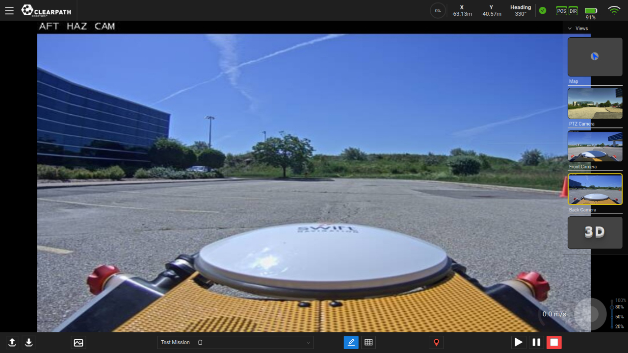
The Web User Interface (Web UI) provides a easy, graphical, means to control both manual and autonomous operation of your UGV. The following sections outline: the components and views of the UI, the details of operating in manual mode, and the details of operating in autonomous mode.
Main Components
-
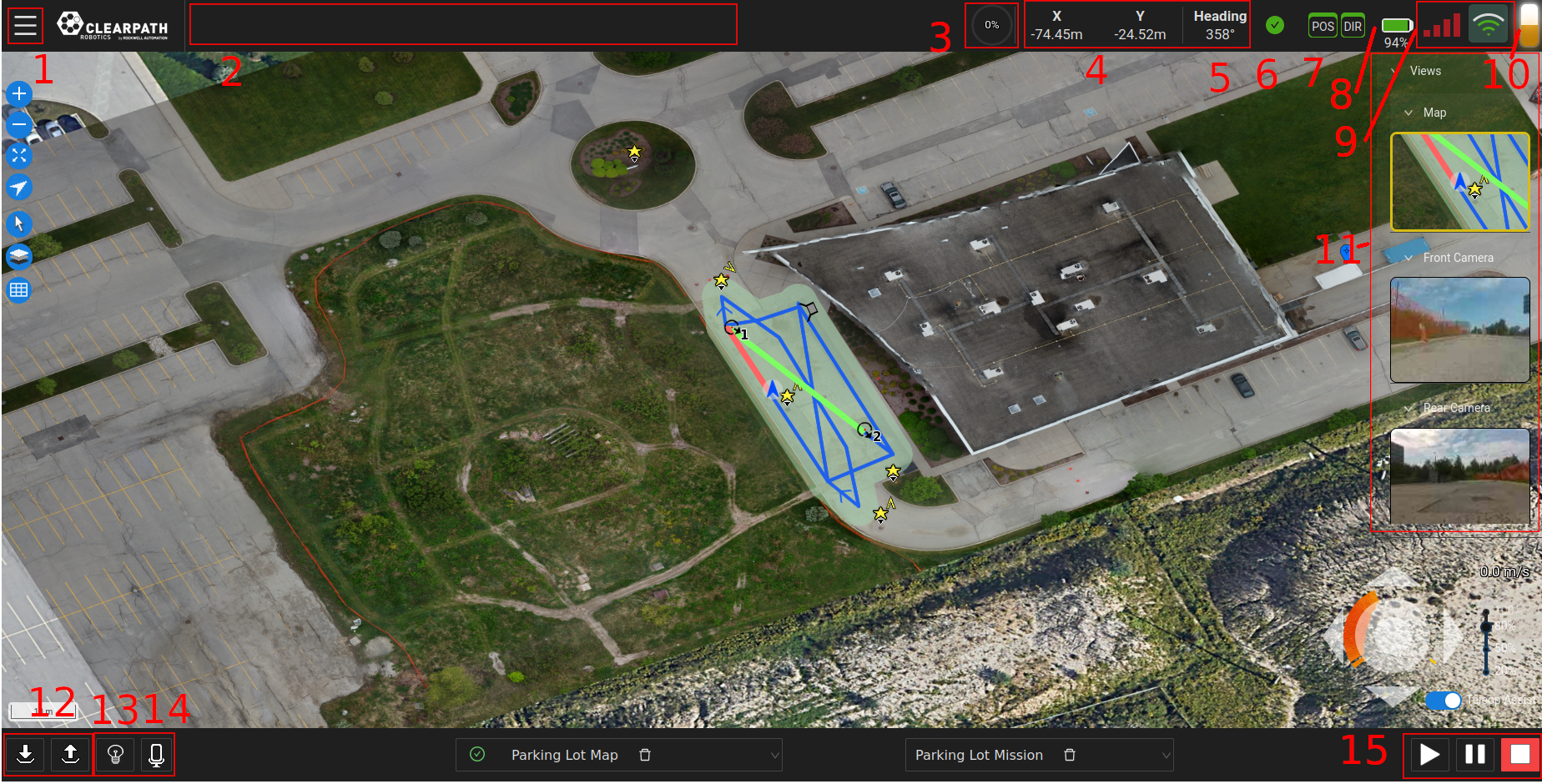
Menu: A dropdown menu allowing the user to access the Dashboard (ie. Home), Settings, Status, Scheduler, Help, and File pages. The User can also run the UI Virtual Tour from this menu.
-
Feedback Bar: The feedback bar will display information regarding the execution state of the navigation and of any Tasks being executed.
-
Path Progress Meter: A meter indicating the percentage complete of a Mission.
-
UGV Position: The UGV's X and Y position in the world frame relative to the Datum. Can also be shown in Lat/Lon coordinates
-
UGV Heading: The UGV's heading in the world frame. 0 degrees is North, 90 degrees is East, 180 degrees is South and 270 degrees is West.
-
Status Indicator: The status indicator will display information regarding various UGV status monitors such as the Emergency Stop, Surveying, etc. When the UGV is fully operational, the indicator will be green. Operators can click on the status indicator to see more details pertaining to the current state as well as past messages.
-
GPS Status Indicator: The GPS status indicators will display GPS signal accuracy for position (POS indicator) and heading (DIR indicator). Green indicators represent RTK accuracy and are currently required for accurate autonomous navigation. Yellow and orange indicators represent SBAS and SPP accuracy respectively and noticeable oscillations may occur in such cases. Red indicators mean no GPS signal and autonomous navigation missions should not be started.
-
Battery Life Indicator: The UGV's battery life indicator.
noteIf the indicator is stuck at 50%, that means that your UGV does not have a supported battery management system and this indicator is not active.
-
Wireless Connection Indicator: The wireless connection indicator represents the signal strength between the wifi access point (typically the Base Station) and the UGV. If the system can support cellular connections a cellular indicator will appear next to the wifi icon with the currently active connection being highlighted in green.
-
Stack Light: If a Stack Light is configured for the UGV its current status will show here.
-
Views List: A dropdown list of available views, detailed later in this section. Some of the available views are Map, and Camera views etc.
-
Local Docking/Undocking: The local docking/undocking buttons used to dock/undock the UGV. The UGV must have it's charging adaptor facing the dock when performing the local dock action.
-
Lights Control: If the UGV is equipped with software controllable lights they can be controlled through a simple drop down button as well as relevant hotkeys, depending on the configuration.
-
Record Audio: If the UGV is equipped with a microphone the user can start/stop recording manually by clicking this icon.
-
Mission Execution Buttons: These buttons allow users to Start, Pause and Stop an autonomous mission.
By opening the dropdown list "Views", on the right side of the UI, the Operator can access the following views:
- Map View
- PTZ Camera View (if available)
- Front/Back Camera View (if available)
Map View
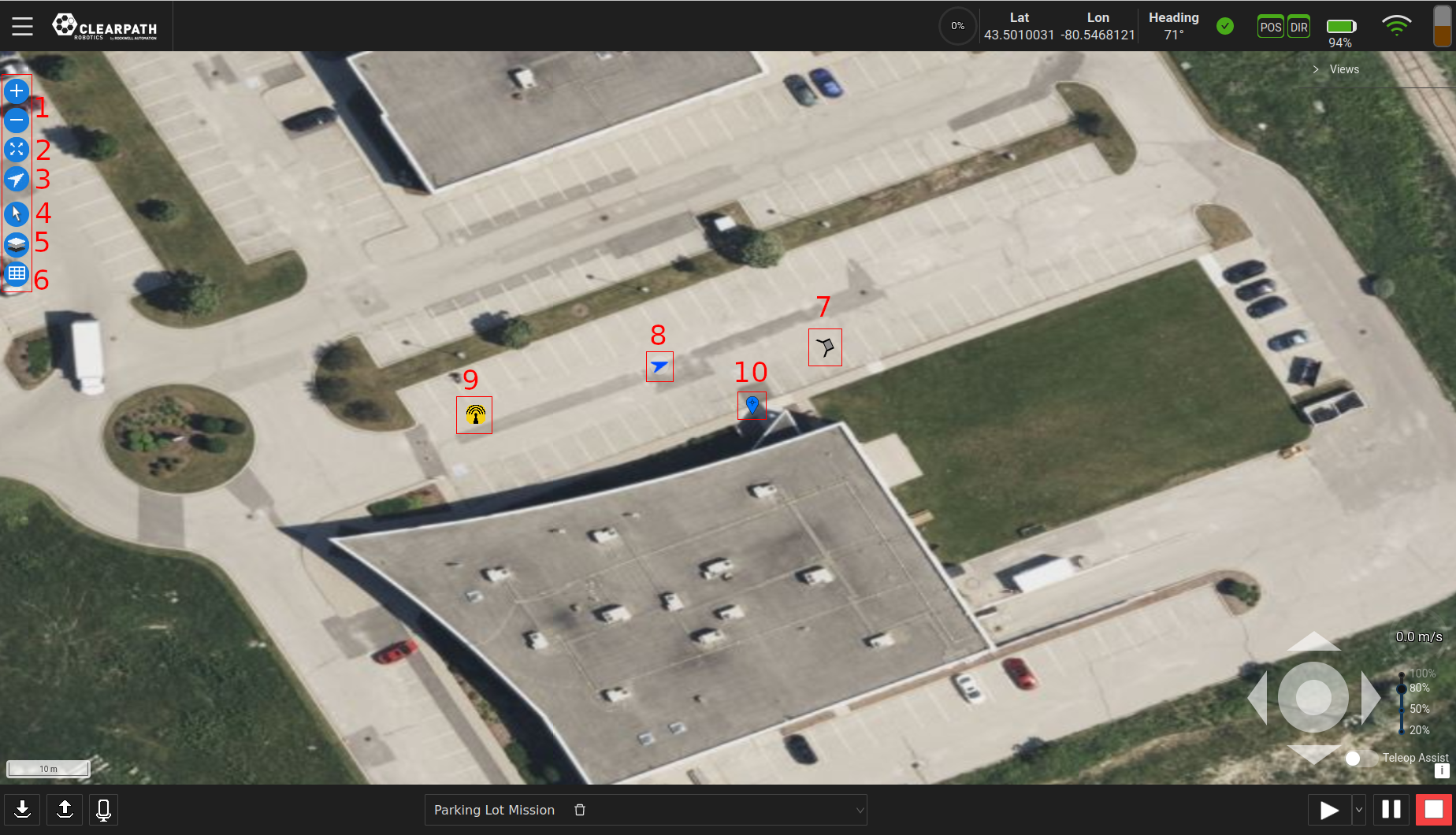
- Zoom Buttons: These buttons allow the user to zoom in/out of the map levels.
- Zoom-to-Fit Button: This button will zoom the map to where there is activity (ie. where the datum is set or where features have been set on the map.)
- Zoom-to-Robot Button: This button will zoom the map to where the UGV is presently located.
- Edit Mode Buttons: This button will allow the user to set the current map edit mode.
By clicking the button, a panel opens on the right with the available modes to edit with.Changing Edit Modes - Layers Menu: This button opens the Layers menu which allows users to show and hide elements on the map.
Points of interest in particular can be hidden by tags specifically as well as generally hiding them.
Hiding and Showing Layers - Table Button: This button opens the Map/Mission table. When in Waypoint Mode it will open the table directly, while in Map mode it will allow users to select the table to open or open a table based on which mode is being editted.
- Dock: If a dock is configured for the UGV it will appear on the map in this format. When in Waypoint mode the Docks pre-dock radius will appear as a circle around the dock when in Edit Mission mode.
- UGV: The blue arrow represents the UGV. Its location is its position in the world frame and its orientation is the heading in the world frame.
- Base Station: The yellow antenna icon is the last known location of the base station based on the last survey performed. By clicking it the user will be presented with the base station's coordinates, when it was surveyed, and how many samples were taken during the survey.
- Datum: The blue Waypoint marker on the map view represents the location of the reference point (ie. (x,y)=(0,0)) of the world coordinate system. The world (ie. map) coordinate system is in the ENU convention.
Camera Views
If PTZ and/or Front/Back camera(s) are included on the UGV, their feeds can be viewed through the UI and the PTZ can be controlled through the UI. If not, there will not be any PTZ, Front/Back view(s) in the list of available views.
Pan-Tilt-Zoom (PTZ) View
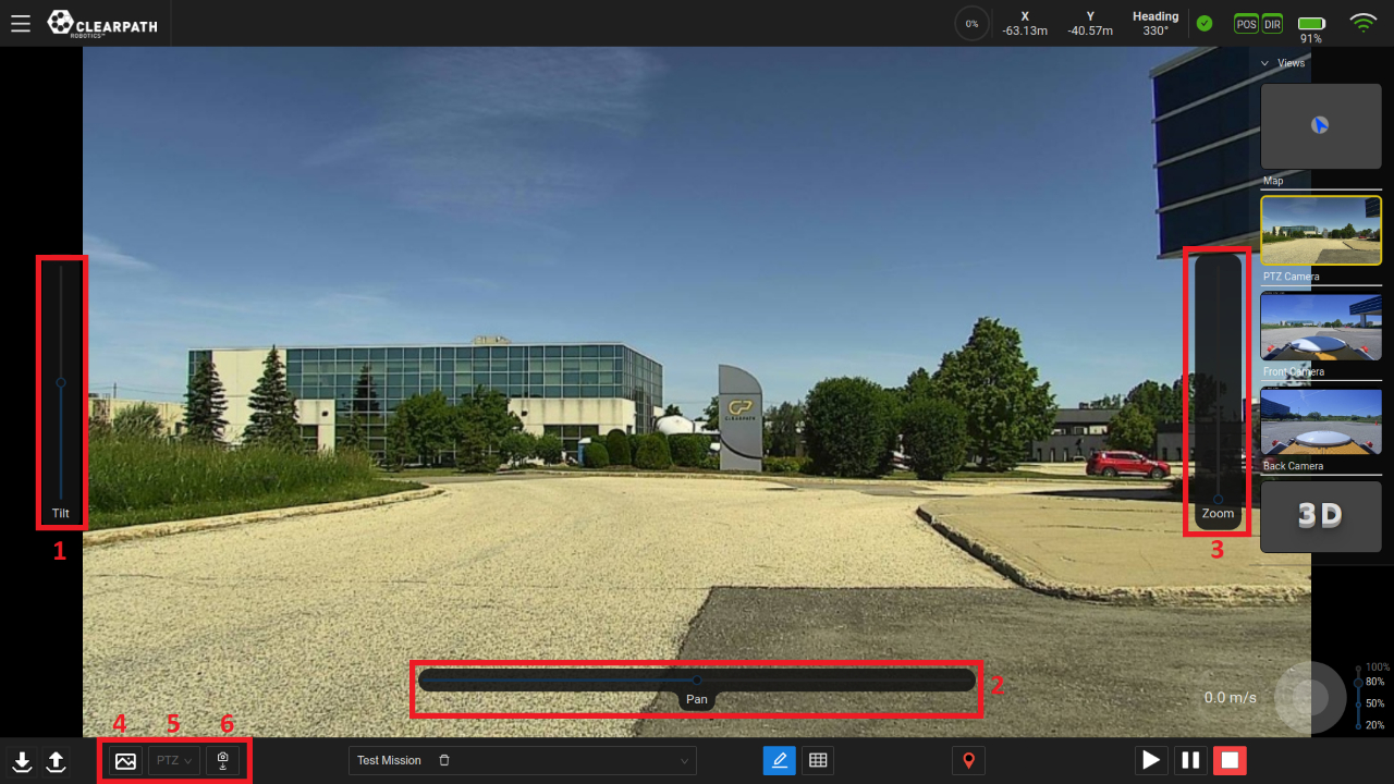
- Tilt Slider: The left slider can be used to tilt the camera in a vertical motion, (ie. upwards or downwards motion). By default, the slider is at its neutral ("zero") position.
- Pan Slider: The bottom slider can be used to pan/rotate the camera, (ie. rotational motion). By default, the slider is at its neutral ("zero") position.
- Zoom Slider: The right slider can be used to zoom the camera feed. By default, the slider is at its neutral ("zero") position.
- Save Image: Depending on the current camera view selected, this button will save an image to the computer/tablet running the UI. Images will be saved to the location in which your browser saves files.
- Camera Positions List: Display the list of available camera positions that have been saved. These camera positions can be deleted from this list by clicking the "garbage can" icon beside the corresponding position.
- Save Camera Position: This button will save the camera position
to be used in the "Move PTZ" task. An example use case would be:
- Switch to the PTZ camera view.
- Teleoperate the UGV to a location at which the user can inspect something.
- Move the camera sliders to orient the camera such that it is looking at the inspection point.
- Click the "Save Camera Position".
- When creating an autonomous mission to this inspection point, add the "Move PTZ" task to a Waypoint.
- Click the settings button beside the task and add the camera position related to the inspection point.
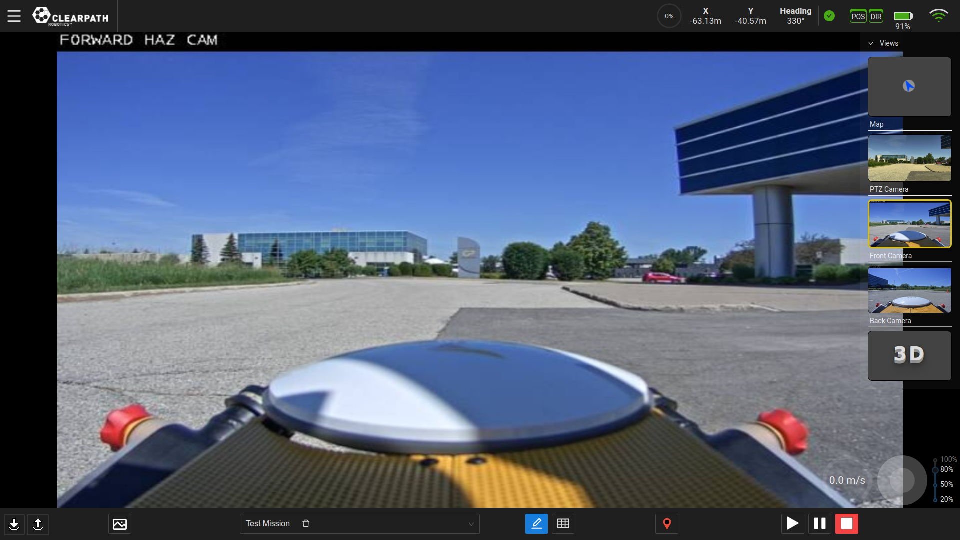
Front and Back Views
System Configuration
General Settings
The General settings section can be found accessing the Menu → Settings → General and allows the user to modify some general settings, both for the UI and the UGV.
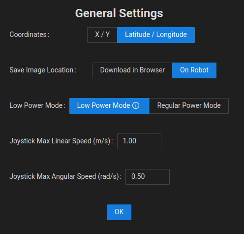
Coordinates
The Operator can change the coordinate space from X/Y relative to the Datum to Latitude/Longitude.
Save Image Location
The Operator can choose to store images saved manually to the robot directly or to download them onto their computer. This feature only affects the manual save image option found on each relevant camera view.
Robot Internet Connection Type
If the UGV is equipped with SIM card and can switch between Cellular and WiFi connections, the Operator can manually trigger this change through the general settings page. This switchover will take approximately 30 seconds and will require a refresh on the UI.
Low Power Mode
If the UGV is equipped with a Low Power Module this toggle allows the user to switch the UGV into a low power state that will drastically limit functionality but help conserve power. This mode is best used to help better facilitate charging while the UGV is not in use.
Joystick Max Speeds
The Operator can choose to set the Maximum Linear Speed and the Maximum Angular Speed that the teleoperation will use. These are limited to the maximum speeds of the UGV itself.
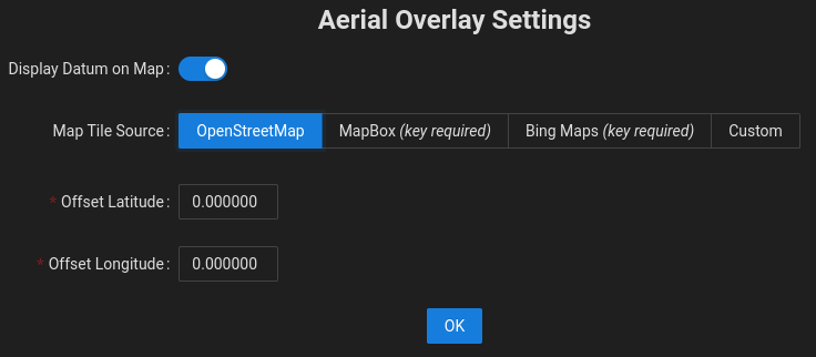
Aerial Overlay Settings
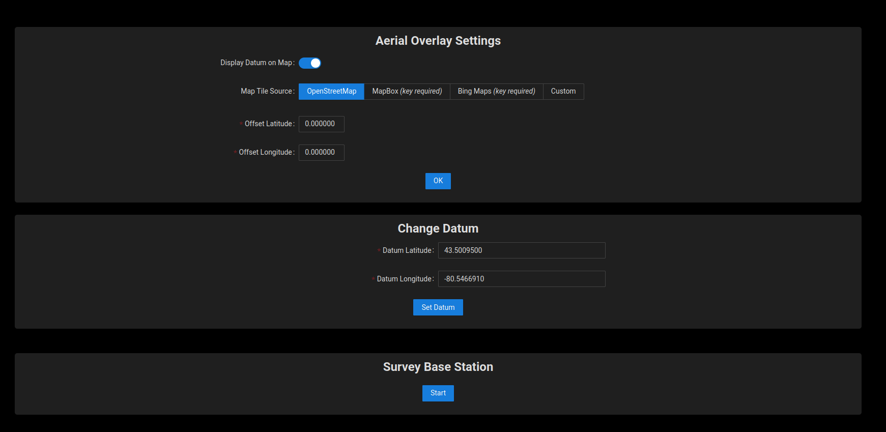
To access the Aerial Overlay Settings: Menu → Settings → Aerial Overlay:
- Offset: The map tiles used in this software are not perfectly aligned with the real world. Therefore, the user may need to apply an offset to the map so that the UGV's position in the real world matches its position on the map.
- Change Datum: The datum is represented by a blue marker on the map and should be set to a location within 10km of the test site. The user can change this value in the Map Settings page. Enter the new values and click the "Set Datum" button.
- Survey Base Station: This button starts the survey process, which takes about 5 minutes to complete. Updated RTK corrections are sent to the position GNSS unit once the surveying has completed.
Map Source Configuration
The Web UI ships with access to free OpenStreetMap maps. Aerial view requires access to third-party aerial maps or your own aerial maps.
The Web UI is pre-configured to work with MapBox and Bing Maps once a suitable map key has been acquired. Both services offer a free tier that will be sufficient in almost all cases.
Using OpenStreetMap Maps
As no key is required to use OpenStreetMap maps, the process to select these maps in the Web UI is simple.
- In the Web UI, from the menu, select Settings→Map to bring up the Map Settings page.
- Select OpenStreetMap
- Click Ok.
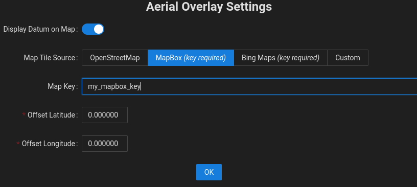
Using MapBox Maps
Using MapBox maps requires a key, which can then be used by the Web UI. The steps to set up MapBox are outlined below.
- Acquire a MapBox key from the MapBox website. Review the license terms and select the appropriate plan. In most cases, the free tier will be sufficient.
- Back in the Web UI, from the menu, select Settings→Map to bring up the Map Settings page.
- Select MapBox.
- Copy the MapBox key from Step 1 into the Map Key field.
- Click Ok.
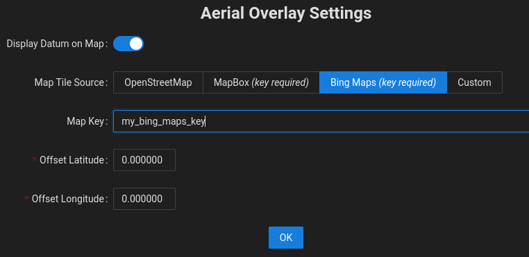
Using Bing Maps
Using Bing Maps requires a key, which can then be used by the Web UI. The steps to set up Bing Maps are outlined below.
- Acquire a Bing Maps key from the Bing website. Review the license terms and select the appropriate plan. In most cases, the free tier will be sufficient.
- Back in the Web UI, from the menu, select Settings→Map to bring up the Map Settings page.
- Select Bing Maps.
- Copy the Bing Maps key from Step 1 into the Map Key field.
- Click Ok.
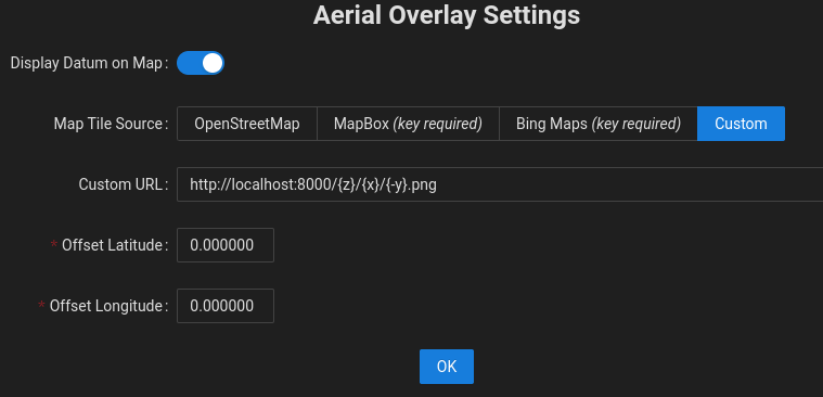
Using Custom Maps��
Custom Maps allow you to use another set of maps in XYZ format, either from a third-party map provider or from maps that you have generated on your own, such as from drone aerial images. Custom maps can be selected by using the steps below.
- Ensure that the maps are accessible on an internal network or on the Internet by the device that is being used to display the Web UI, such as a laptop, tablet, or desktop computer.
- Ensure that the directory structure for the individual tiles is well defined. See the section below for details on Preparing Custom Map Tiles from Drone Aerial Images.
- In the Web UI, from the menu, select Settings→Map to bring up the Map Settings page.
- Select Custom.
- Enter the network path for the maps into the Custom URL field.
If hosting the maps on your local computer, this will be similar to
http://localhost:8000/{z}/{x}/{-y}.png. Note how the
URL is parameterized with
{z},{x}, and{-y}values. This will need to be adapted to match the directory structure of your map tile images. - Click Ok.
Preparing Custom Map Tiles from Drone Aerial Images
In some cases, it is desirable to create your own maps rather than using third party maps which might be outdated. One way to do this is to use a drone to capture aerial images and convert those images into map tiles. While there are many ways to accomplish this, one approach is outlined below.
-
Use a drone to collect top-down photos covering the area of interest. It is highly recommended to use a drone control app that allows you to specify the area of interest and desired image overlap (recommended ~75%) and takes care of coverage planning, drone control, and image acquisition.
-
Perform ortho-mosaicing/ortho-rectification to stitch the collected images together into a single orthographic image. Open Drone Map is a popular open source project that Clearpath has used for stitching, but there are also paid services that automate the process.
-
Georeference the orthographic image. One way to do this is to define the locations of well-defined features (sewer grates, utility holes, etc.) based on their known positions, such as their position data from an existing mapping service (e.g., Google Maps). Open source tools, such as QGIS can help with this process.
-
Generate the map tiles. Using Ubuntu, this can be accomplished with the following commands, where
GEOREFERENCED_IMG.tifis the output of the previous step.sudo apt install gdal-bin
gdal2tiles.py <GEOREFERENCED_IMG.tif> -
Use a web server to host the tiles locally. Using Ubuntu, one way to accomplish this is to use the commands below, which will make the tiles available at: <http://localhost:8000/\>.
cd /base/directory/of/tiles
python3 -m http.server
Once your map tiles are available on the network, you can follow the steps in Using Custom Maps to have the Web UI use your custom tiles.
Autonomy Features
There are presently 2 autonomous modes that the UGV can be used in, Waypoint Mode and Map Mode.
While each mode leverages different features, some are shared and are elaborated on here.
Some objects that appear on the overlay have context menus associated with them. However there is a known issue related to opening this context menu between Autonomy modes. At present to open a context menu in the Waypoint Mode, left click the object, and when in Map Mode right click the object. This issue will be reconciled in a future release.
Tasks
When running a mission autonomously the user can assign tasks to various events. These tasks, along with their decoration icons, are found below:
-
 Dock Robot:
Will dock the UGV to begin charging the UGV's battery. There are 3 kinds of docking that can be used; Network, Radius and Local. See Autonomous Docking for more information on the autonomous docking feature.
Dock Robot:
Will dock the UGV to begin charging the UGV's battery. There are 3 kinds of docking that can be used; Network, Radius and Local. See Autonomous Docking for more information on the autonomous docking feature. -
 Move PTZ:
Will move the PTZ camera to the position selected in the task settings.
Move PTZ:
Will move the PTZ camera to the position selected in the task settings.Settings: Select the camera position. See Pan-Tilt-Zoom (PTZ) View for details on how to save camera positions.
-
 Save Image:
Will save an image using one of the UGV camera(s) to the /opt/onav/saved_files/media/... directory and can be retrieved using a tool such as FileZilla or by navigating to the Files section in the hamburger menu.
Save Image:
Will save an image using one of the UGV camera(s) to the /opt/onav/saved_files/media/... directory and can be retrieved using a tool such as FileZilla or by navigating to the Files section in the hamburger menu.Settings: Select which camera the image will be saved from.
-

/
 Start/Stop Video Recording:
Will start/stop recording video using one of the UGV camera(s) to the /opt/onav/saved_files/media/... folder and can be retrieved using a tool such as FileZilla or by navigating to the Files section in the hamburger menu.
Start/Stop Video Recording:
Will start/stop recording video using one of the UGV camera(s) to the /opt/onav/saved_files/media/... folder and can be retrieved using a tool such as FileZilla or by navigating to the Files section in the hamburger menu.Settings: Select which camera the recording will come from.
-
 Start/Stop Audio Recording:
Will start/stop recording audio using one of the UGV microphone(s) to the /opt/onav/saved_files/media/... folder and can be retrieved using a tool such as FileZilla or by navigating to the Files section in the hamburger menu.
Start/Stop Audio Recording:
Will start/stop recording audio using one of the UGV microphone(s) to the /opt/onav/saved_files/media/... folder and can be retrieved using a tool such as FileZilla or by navigating to the Files section in the hamburger menu.Settings: Select which microphone the recording will come from.
-
 Undock UGV:
Will undock the UGV from the autocharge dock. Once completed, the UGV can be sent on autonomous missions. It is often recommended to place the undock task first in the list of Waypoints or as a start Mission Task; that way, the UGV will automatically continue towards its next Waypoint once undocked.note
Undock UGV:
Will undock the UGV from the autocharge dock. Once completed, the UGV can be sent on autonomous missions. It is often recommended to place the undock task first in the list of Waypoints or as a start Mission Task; that way, the UGV will automatically continue towards its next Waypoint once undocked.noteIf the users places the Undock Task in the start Mission event for a Waypoint Mission the first Waypoint should be approximately 2-3 meters behind the UGV's docked position.
-
 Wait:
Will pause and wait for the specified number of seconds at the end of the Waypoint.
Wait:
Will pause and wait for the specified number of seconds at the end of the Waypoint.Settings: Enter the amount of time to wait, in seconds.
-
 Inspect POI:
Will move the PTZ camera to inspect a specified Point of interest.
Inspect POI:
Will move the PTZ camera to inspect a specified Point of interest.Settings: Select the inspectable Point of Interest and enter in the zoom level to use.
-
 New Custom Task:
Creates a new custom task that is defined by the user.
New Custom Task:
Creates a new custom task that is defined by the user.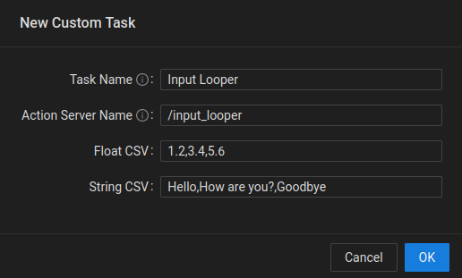
Custom Task Settings Dialog - Task Name: Task name that will show up in the list of available tasks on the UI.
- Action Server Name: The namespace of the custom task action server.
- Float CSV: A list of comma seperated float values that consist of the numerical inputs to the custom task.
- String CSV: A list of comma seperated string values that consist of the semantic inputs to the custom task.
See the Custom Tasks section for details on how to develop custom tasks for your application.
If a Waypoint/Goalpoint has more than one task assigned to it, the icon will
be replaced with a sheet of paper icon like so: 
Points of Interest
Users are now able to add Points of Interest (POI) onto their map, marking a location or an object that is persistent across both "Map" and "Waypoint" planning modes. The intended use for the points of interest feature is to allow the user to set up locations that they know will almost never change and be able to for example navigate, inspect these locations.
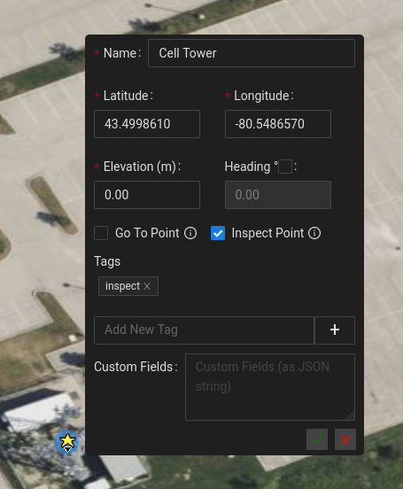
Creating POIs
To create a POI, ensure that you are in "POI edit mode" (Hotkey, e+4). Click on the map to place your POI and assign the POI a name. You also have the ability on creation to assign a heading, tags and custom fields (all optional).
Editing POIs
To edit an existing POI, right click the POI and select Edit. This will allow you to modify any of the existing properties of the POI. If you want to simply modify the heading of a POI, you can use the CTRL hotkey to enable heading modification and rotate the POI to your desired heading. See video below for an example of the editing the heading of a POI using the (CTRL hotkey).
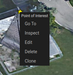
Predefined actions
If a POI is assigned one of the two predefined tags, goto and/or inspect, the user will have the ability to perform
some quick actions when they right click the POI. In "Map mode" only, not in "Waypoint mode", if the POI has a goto tag,
the user will see a Go To option in the right click options that will autonomously navigate the UGV to the location of
the POI (if it is within the bounds of the current network). If the POI has an inspect tag, the user will see an Inspect
option in the right click options that will move the PTZ camera to view the POI when clicked. See the below image for an
example of a POI that has both the goto and inspect tags, and therefore has the Go To and Inspect action options
when right clicked.
Creating Missions from POIs
If the user wants your UGV to navigate to a set of predefined locations they can create POI's for each of these stops and leverage them accordingly. By entering the network mission edit mode (hotkey: e+3), the user can simply click on the POIs in order of traversal to create your network mission. The network goals that are created on each click of a POI will place a Goal at the exact location of the POI and will also use the heading that has been defined by the POI.
Autonomous Docking

Docking The UGV
To dock the UGV autonomously the user can use the following methods:
Dock (Local)
If there is a valid dock within its driveable range the UGV will attempt to dock. This docking method can be done by selecting the Dock button in the bottom bar or by adding a "Dock Robot (Local)" task to either an event or a mission point.
Dock (Radius)
If the UGV is within the specified docks radius the UGV will first navigate to a predock location and then attempt to dock. When in Waypoint Mode a user can dock via this method as follows:
- Enable the "Edit Mission" toggle.
- Maneuver the UGV so that is somewhere within the dock's radius.
- Click the dock that the UGV will be docking at and select "Dock Robot Here".
This docking method can also be accomplished by adding a "Dock Robot (Radius)" task to either an event or a mission point. A dock will need to be provided for the task to function which can be done through the task settings modal.
Dock (Network)
This mode is only available in Map mode. Please see the Map mode page for further details on map generation.
If the UGV and the dock are within a map's driveable area the UGV will first navigate to a predock location based on the map paths available. A user can dock manually using this method as follows:
- Enable the "Edit Map" toggle.
- Maneuver the UGV so that is within the driveable range of the map.
- Ensure the dock is within the driveable range of the map.
- Right click the dock that the UGV will be docking at and select "Dock Robot Here".
This docking method can also be accomplished by adding a "Dock Robot (Network)" task to either an event or a mission point. A dock will need to be provided for the task to function which can be done through the task settings modal.
Undocking The UGV
To undock the UGV autonomously, the user can apply a "Undock Robot" task to a mission event or point. The user can also click the Undock button in the bottom bar's left hand corner.
Compatibility with a Doghouse
In order for the autonomous docking feature to be compatible with a doghouse, the doghouse must conform to a few specifications:
- Must be installed on a flat surface, and have no elevation change between the charge-dock and the outdoor surface (ie. no ramp into the doghouse).
- Must be greater than 1.2 m wide.
- Must be between 1.5 and 2.5 m long.
- Dock target should be installed centered along the back of the doghouse.
Recover from Failed Docking or Undocking
If for any reason, the docking or undocking tasks fail, the user can:
- Manually drive the UGV towards the dock target, aligning the charging unit with the receiver on the UGV.
- Manually drive the UGV in reverse away from the dock target. It is suggested that the user reverse roughly 2-3 meters away from the target, then wait 1-2 minutes before starting any autonomous navigation missions.
Switching to IndoorNav
If it is included in the UGV, IndoorNav can be executed through the OutdoorNav software. To switch between the modes in OutdoorNav select the 'Navigation Mode' option found in the hamburger menu. This will navigate to a page that shows the current mode and provides an option to switch. When in IndoorNav mode the user may navigate to the IndoorNav Web GUI directly or work within the OutdoorNav view as can be seen below.
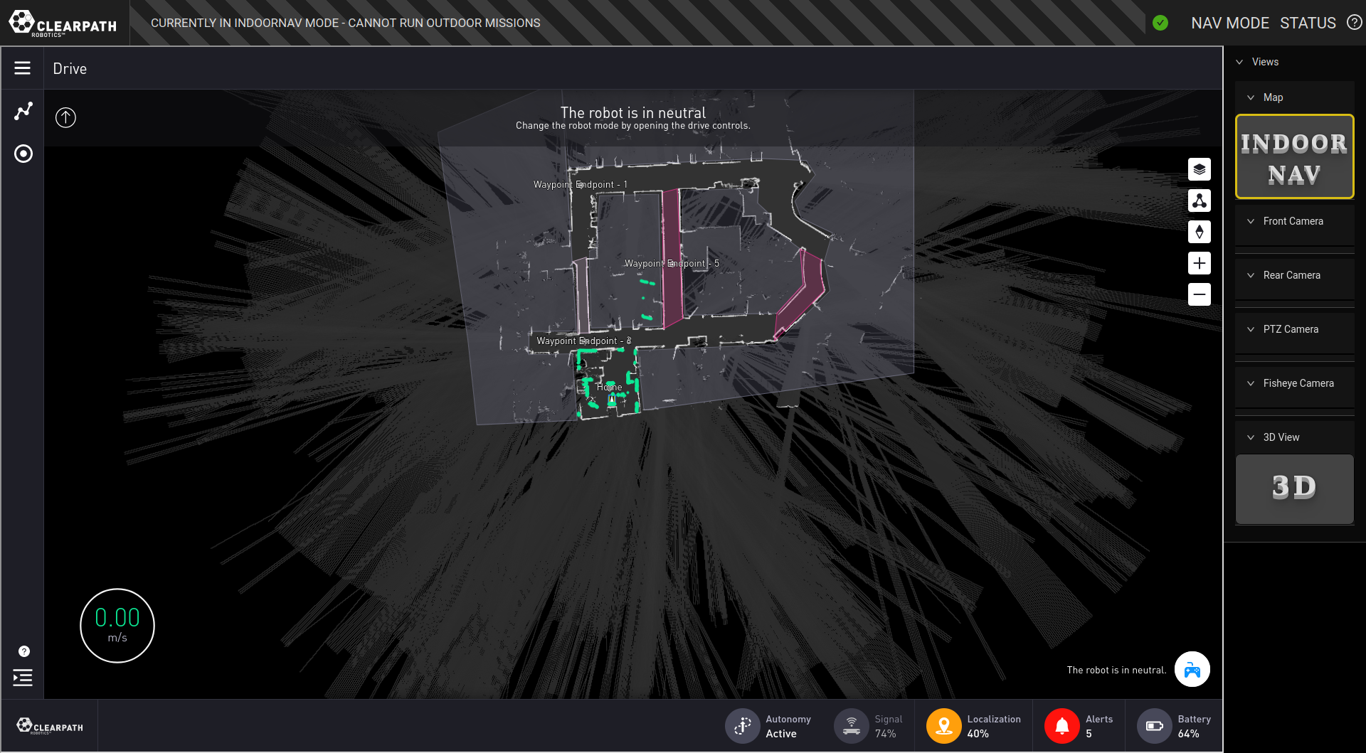
When in IndoorNav mode the OutdoorNav Autonomy software is switched off. The UI will disable OutdoorNav UI features related to Autonomy but will still allow users the option to view camera streams.