Getting Started
This section outlines how to set up your OutdoorNav system for initial testing.
- Ensure that the UGV is powered on.
- If the optional Base Station is included, ensure that it is also powered on.
Networking Setup and UI Access
It is possible to use either a Windows or a Linux PC to connect to the robot and OutdoorNav user interface (UI). There are a few different ways to connect/communicate with the robot, each have their pros/cons. Below, each method is listed with instructions on how to access the UGV.
Via Ethernet
Via Ethernet
Connecting to the robot via the ethernet port allows for the fastest connection speed, ideal for transferring large files and for quick/easy access to the robot. It is not possible to connect via ethernet if you wish to run any Outdoornav missions.
-
Connect an ethernet cable between your PC (Windows/Linux) and the ethernet port on the rear of the robot.
-
Set up the ethernet port on your PC to have a static IP address on the 192.168.131.XXX subnet (eg. 192.168.131.200)
-
Open a terminal (Linux)/command prompt (Windows) and test the communication between your PC and the robot PC
ping 192.168.131.1 -
If the ping test is successfull and you are receiving replies, then you can SSH into the robot's PC and access the UI at the following,
SSH (password) ssh robot@192.168.131.1(clearpath)UI (URL) http://192.168.131.1 If the ping test was unsuccessful, then confirm that you have set up your ethernet interface properly to have a static IP on the correct subnet 192.168.131.XXX (eg. 192.168.131.200)
ifconfig (Linux)
ipconfig (Windows)
If you are still having issues, please contact Support.
Access the Robot Peplink
| Peplink (URL) | http://192.168.131.51 |
| Username | admin |
| Password | Clearpath123 |
The robot PC will not have internet access unless you have connected the onboard robot Peplink to an internet source (ie. connecting via wifi or by adding a SIM card and connecting to a carriers network)
To connect the robot Peplink to a internet source follow these instructions.
Via the Robot's wireless network
Via the Robot's wireless network
Each OutdoorNav robot contains a Peplink MAX BR1 Pro 5G router which is configured to act as a wireless access point. Connect your PC to the following wifi source (SSID):
| SSID | cpr_a300_amp_XXXXX |
| Password | clearpath |
Depending on whether or not a base station is included with your robot there will be two different configurations. Follow the tables below based on whether or not you have a base station included.
Access the Robot/UI
| Base Station NOT included | Base Station included | |
|---|---|---|
| DHCP Lease | 192.168.131.XXX | 192.168.130.XXX |
| SSH (password) | ssh robot@192.168.131.1 (clearpath) | ssh robot@192.168.130.201 (clearpath) |
| UI (URL) | http://192.168.131.1 | http://192.168.130.201 |
Access the Robot Peplink
| Base Station NOT included | Base Station included | |
|---|---|---|
| Peplink URL | http://192.168.131.51 | http://192.168.130.129 |
| Username | admin | admin |
| Password | Clearpath123 | Clearpath123 |
The robot PC will not have internet access unless you have connected the onboard robot Peplink to an internet source (ie. connecting via wifi or by adding a SIM card and connecting to a carriers network)
To connect the robot Peplink to a internet source follow these instructions.
Via a CPR provided Base Station
Via a CPR provided Base Station
If you have purchased a seperate (optional) Base Station, it will be configured to act as the a wireless access point for your robot.
- Place the base station outside with a clear view of the sky. It should be at least 5m away from large buildings or trees.
- Power on the base station.
- The base station will automatically connect to the robot and provide a wifi network for you to connect to.
- The base station will also automatically start an auto-survey and will start providing an RTK fix to the robot in approx. 10 - 15 minutes.
If you move the base station while it is still powered on, it will need to be powered off and back on again to re-survey and provide an accurate RTK fix.
Connect your PC to the following SSID:
| SSID | CPR-Base-Station |
| Password | clearpath |
Your PC will automatically be assigned a DHCP lease and an IP on the 192.168.130.xxx subnet.
FOr more detailed information on the CPR base station, refer to the Base Station User Manual.
Access the Robot/UI
| SSH (password) | ssh robot@192.168.130.201 (clearpath) |
| UI URL | http://192.168.130.201 |
Access the Base Station Peplink
| Peplink URL | http://192.168.130.1 |
| Username | admin |
| Password | Clearpath123 |
The robot PC will not have internet access unless you have connected the onboard robot Peplink to an internet source (ie. connecting via wifi or by adding a SIM card and connecting to a carriers network)
To connect the robot Peplink to a internet source follow these instructions.
Via Cellular
Via Cellular
Connecting via cellular is likely the most versatile method for deployment of your robot. It allows the robot to access the internet to receive RTK corrections and also allows for remote access, almost anywhere in the world.
Requirements:
- SIM card with a data plan (prepaid or plan) from a local network provider.
- A tunnelling software (eg. Cloudflare)
Getting Internet Access
Connect Robot Peplink to Wifi
The first option is to connect the robot Peplink radio (client) to a wifi source.
- Access the robot Peplink via one of the methods above
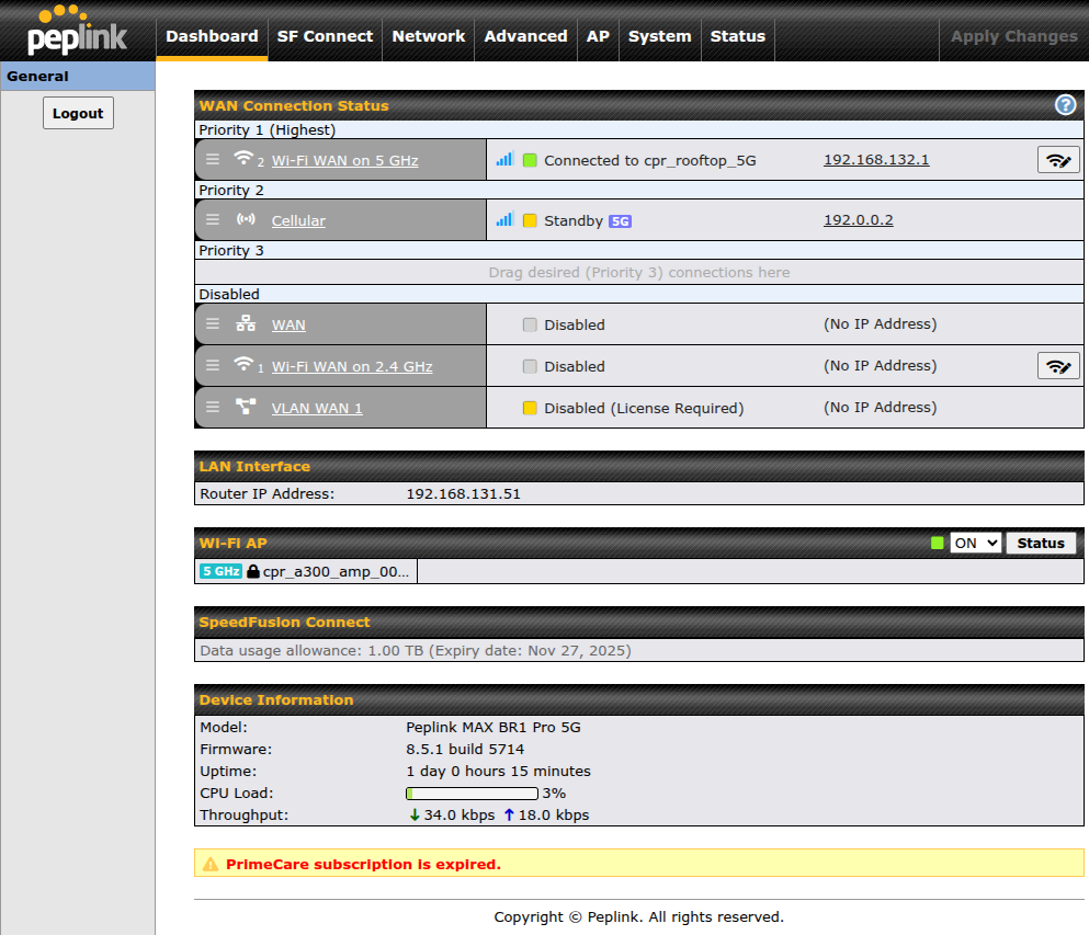
- Depending on the type of Wifi network you are connecting to (2.4 or 5 GHz), you will click on
the appropriate
Wi-Fi WAN on X GHzconnection in the list of connections. - Toggle the
Enablefield. - Scroll to the bottom of the
WAN Connection Settingsto theWi-Fi Connection Profilessection. - Click
Create Profile...
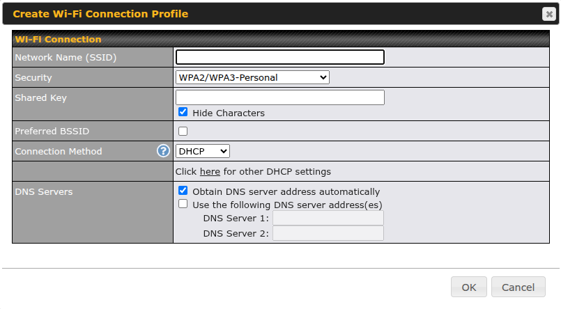
- Fill in all the required fields for the wifi network you are connecting to. Click
OK. - Click
Save and Applyat the bottom right of theWAN Connection Settingspop-up. - Click
Apply Changesat the top right of the dashboard page. The peplink should be trying to connect to the SSID of the profile you created.
Add a SIM card to the Robot Peplink
Use an existing SIM card or purchase a SIM card to be used for internet access to the robot.
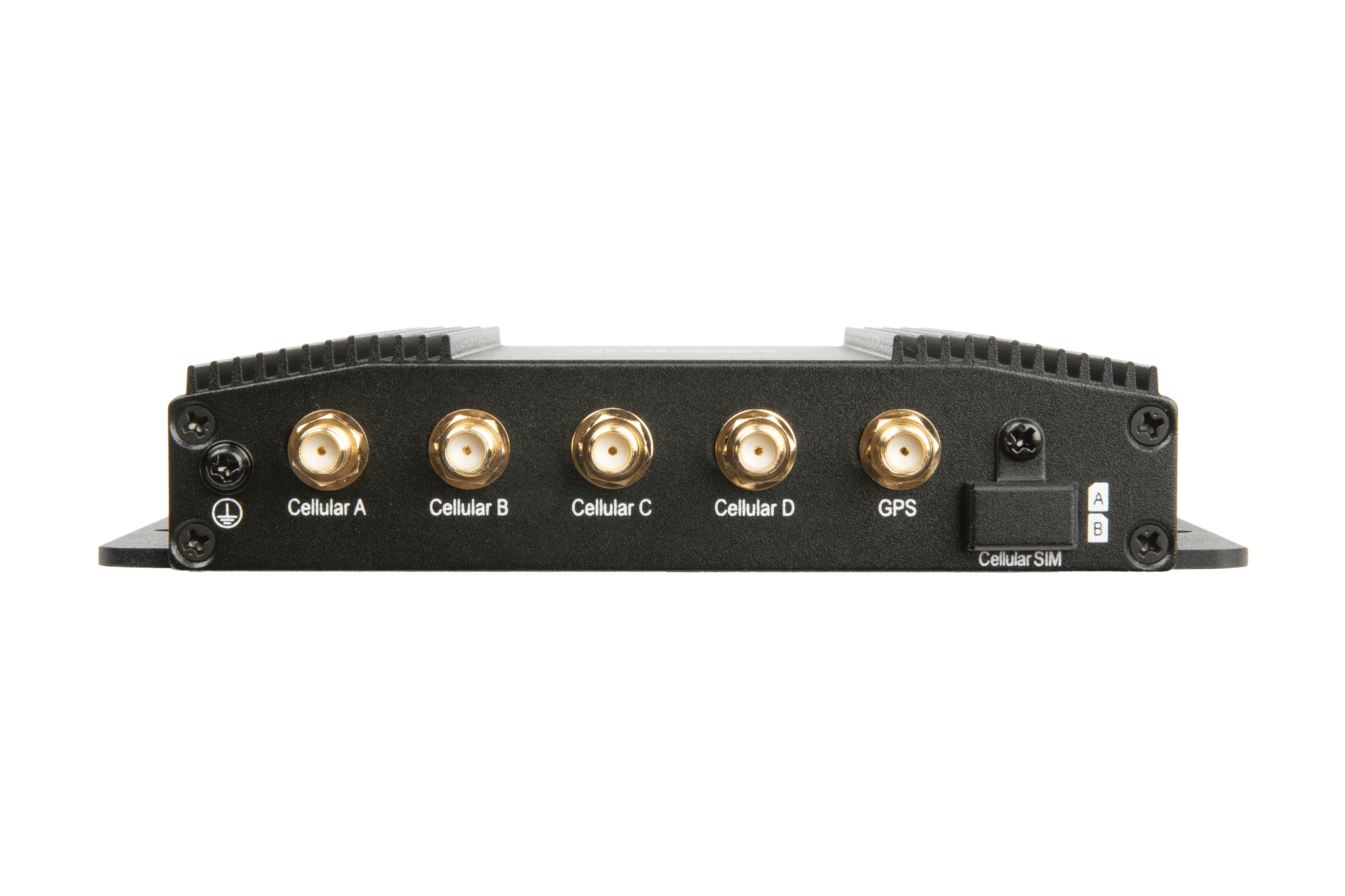
- Insert the SIM card into Slot A or B on the peplink (under screwed cover labeled
Cellular SIM)
- Access the robot Peplink via one of the methods above.
- Click on the
Cellularconnection in the list of connections on the dashboard. - Ensure that the
Enablefield is toggled to ON. - Click
Save and Applyat the bottom right of theWAN Connection Settingspop-up. - Drag and dro whatever connection is in the priority 1 slot and drag and drop the cellular connection to priority 1.
- If you have added a data plan enabled on your SIM card, then it should automatically connect to the carriers network and provide an IP in the connections list.
- If you click the IP address it will pop-up all of the details of the cellular SIM.
Connect Base Station to Internet
There are two different ways to connect the base station to the internet, either via wifi or by adding a SIM card to the Base Station Peplink. They are listed below.
-
You can insert a SIM card into the Base stations Peplink in a similar manner to the section above.
-
You can connect the
WANethernet port on the side of the base station to a live internet connection (physical ethernet cable) and the Base Station should be granted an IP address via DHCP. If the Base Station is not able to connect to the Internet, or is not granted a WAN IP address, contact your network administrator in case additional login credentials are needed.
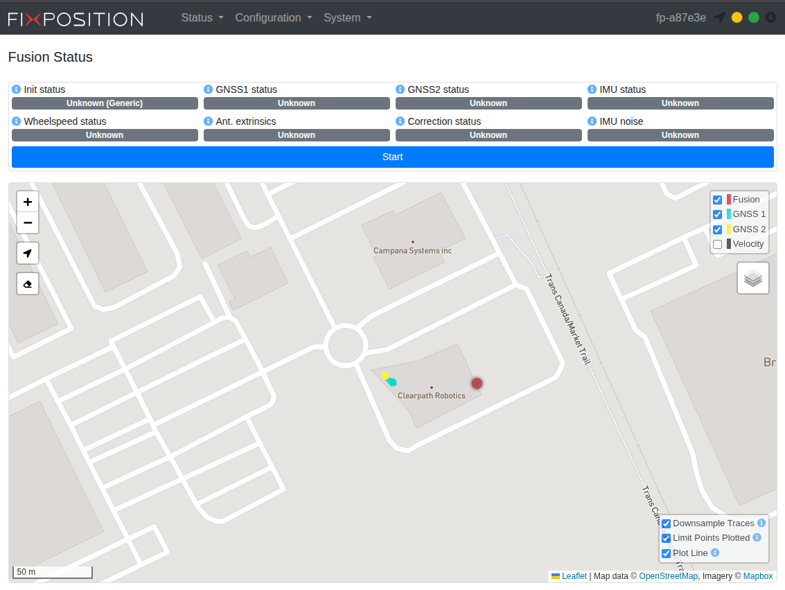
RTK Corrections Setup
RTK corrections are required in order for the XVN to output a localization. OutdoorNav will not work if you do not have RTK corrections set up.
- Open the OutdoorNav UI. Click one of the GNSS status indicators and then click the
Open XVN UIbutton. - In the XVN UI, navigate to Status (top bar) -> Fusion. Click the
Stopbutton to stop the fusion. - Navigate to Configuration (top bar) -> GNSS
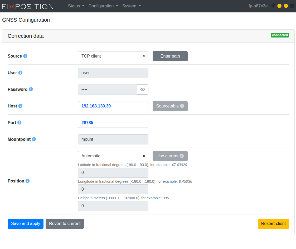
- Enter the details below depending on your connectivity source.
- Click
Save & Apply.
- Confirm connection to RTK correction server.
- The
Correction dataindicator will turn green and sayconnected. - You should also check the Status -> GNSS page and confirm that
good/completecorrections have been comming in for at least one minute.
- Restart the fusion by navigating to Status (top bar) -> Fusion and clicking the
Startbutton. You should start seeing the indicators on the page start turning green as the fusion starts converging.
RTK via CPR Base Station
Via CPR Base Station
| Source | TCP Client |
| User | user |
| Password | pass |
| Host | 192.168.130.30 |
| Port | 28785 |
| Mountpoint | mount |
RTK via Correction Service
Via Correction Service
Below are a list of RTK correction services that are available depending on the region:
- ublox PointPerfect
- Canada, US & Europe
- Japan & South Korea
- Australia
- Brazil & Argentina
- Point One Navigation
- Canada & US (few cities in Mexico)
- Europe
- Japan & South Korea
- Australia
- RTK Data
- Canada, US & Mexico
- Europe
- Australia
- India
- Japan, & South Korea
- Central, South America & South East Asia (major/minor cities)
- Africa (some major cities)
- Some governments operate base stations around the world
- RTKLib
- open-source
- no guarantee that they are maintained or continually operated
- Others available...
The service will provide you with the following information to be entered in the XVN UI:
| Source | NTRIP client (auto) |
| User | To be provided by service once subscribed |
| Password | To be provided by service once subscribed |
| Host | To be provided by service once subscribed |
| Port | To be provided by service once subscribed |
| Mountpoint | To be provided by service once subscribed |
Check the Localization Status GPS RTK Fix
The POS (position), DIR (heading), and FUS (sensor fusion) GNSS status indicators on the UI
should be green: 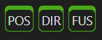 .
.
If the GNSS status indicators are yellow or red, the selected location does not have an adequate GPS signal. Move the UGV such that the GNSS antennas have clearer visibility to satellites.
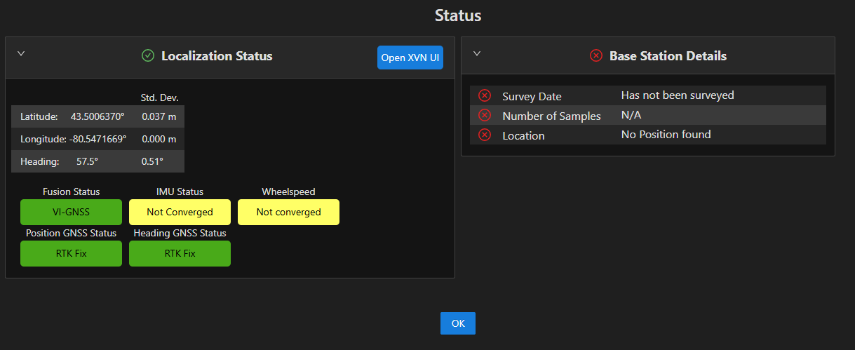
Click any of the GNSS status indicator buttons or Navigate to
Menu → TOOLS → Status Monitor to display the system status. All 5 localization
statuses should be green. If the IMU Status and/or the Wheelspeed statuses are not green they should
turn green once the robot drives around a little while, until the two IMU and wheel encoder data have
converged.
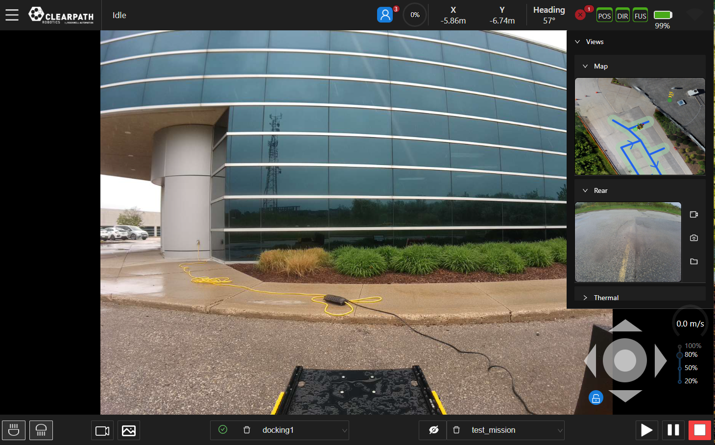
Check Camera Views
All AMP robot include a front and rear Oak-D Pro W PoE cameras. The Observer upgrade also includes an Axis Q62 camera. The live view from each camera is shown on the right side of the OutdoorNav dashboard. Clicking on a camera view will maximize it on the screen. Cycle through each camera view and confirm that it is providing live updates.
Refer to Camera Views for more details.
Complete the System Configuration
Load Map Tiles
The Web UI does not cache map tiles on the browser; therefore, the user will need to ensure their computer has a connection to an Internet source to load the map tiles. There are a several options to achieve this:
- If the system includes a Base Station that is connected to the Internet, you will be able to access the Internet and therefore map tiles over the base station network without needing any further updates.
- Connect your phone via USB to your computer (or tablet) and enable USB tethering on your phone to share the Internet from your phone.
- Switch your computer (or tablet) to a network that is connected to the Internet, zoom in/out of the map to load the tiles then switch back to the original network.
Set Datum
Navigate to Menu → Settings. In the Map Settings section, enter the latitude
and longitude of the datum you want to set. The datum will represent the (x,y) = (0,0) map coordinate frame
origin and must be set within 1 km of your deployment location.
Set Dock Location
If the autonomous docking package has been included, follow these instructions to set up the dock location. Otherwise, this section can be skipped.
Keep the area around the dock free of objects and people. There is no obstacle detection between the pre-docking point and the dock; similarly, there is no obstacle detection during the undocking operation.
Before being able to dock the UGV autonomously, set up the dock location. Follow these steps to position the UGV in its correct position and orientation.
-
Power ON the UGV and wait for the system to finish booting.
-
Start by manually driving the UGV to the dock target and align it as straight and centered as possible so that it begins charging.
-
On the left side of the UI, select the Edit mode button (pencil icon) and then select the Docks option.
-
Click anywhere on the map to create a dock. Name it and select the default configuration.
-
Click and drag the dock to the location of the robot icon and align its position and orientation. To rotate the dock, hold the
Ctrlbutton and use the cursor to orient the dock (the arrow on the dock should be used as a guide). -
On the left side of the UI, select the Edit mode button and then select the cursor option.
-
With the remote controller, drive the robot at low speed purely in reverse so the robot icon on the UI lines up with the green dot on the UI (ie. the predock point).
-
Right click the dock and select
Surveyin the list of option. -
The docks position/orientation will be updated in 10 seconds. You should see the dock snap to its new pose.
Create Your First Map
- Ensure that the UI is in "Map Edit Mode":
 →
→
 .
. - Open the drop down menu in the bottom bar (left-side) and select the "Add Map" option.
- Start placing points and building paths. (A map will be created with the default settings.)
For more details, refer to Map Creation.
Create Your First Mission
- Ensure that the UI is in "Mission Edit Mode":
→
 .
. - Open the drop down menu in the bottom bar (right side) and select the "Add Mission" option.
- Select the "Goalpoint Mode" button.
- Click on the map to add a goalpoint.
- Confirm that a preview path is shown on the map.
For more details, refer to Mission Creation.
Execute a GoTo
- Right-click on a location within the map (ie. anywhere that is in the green navigable space).
- Select
GoTo, a previewed path will show up. If you approve of the path that the robot will traverse, click the checkmark. The robot will begin navigating to the selected point.
Execute Your First Mission
- In the bottom bar of the UI, click the
Playbutton .
. - Confirm that the "Play" button has turned green, which indicates that the mission has started.
For more details, refer to Mission Execution.